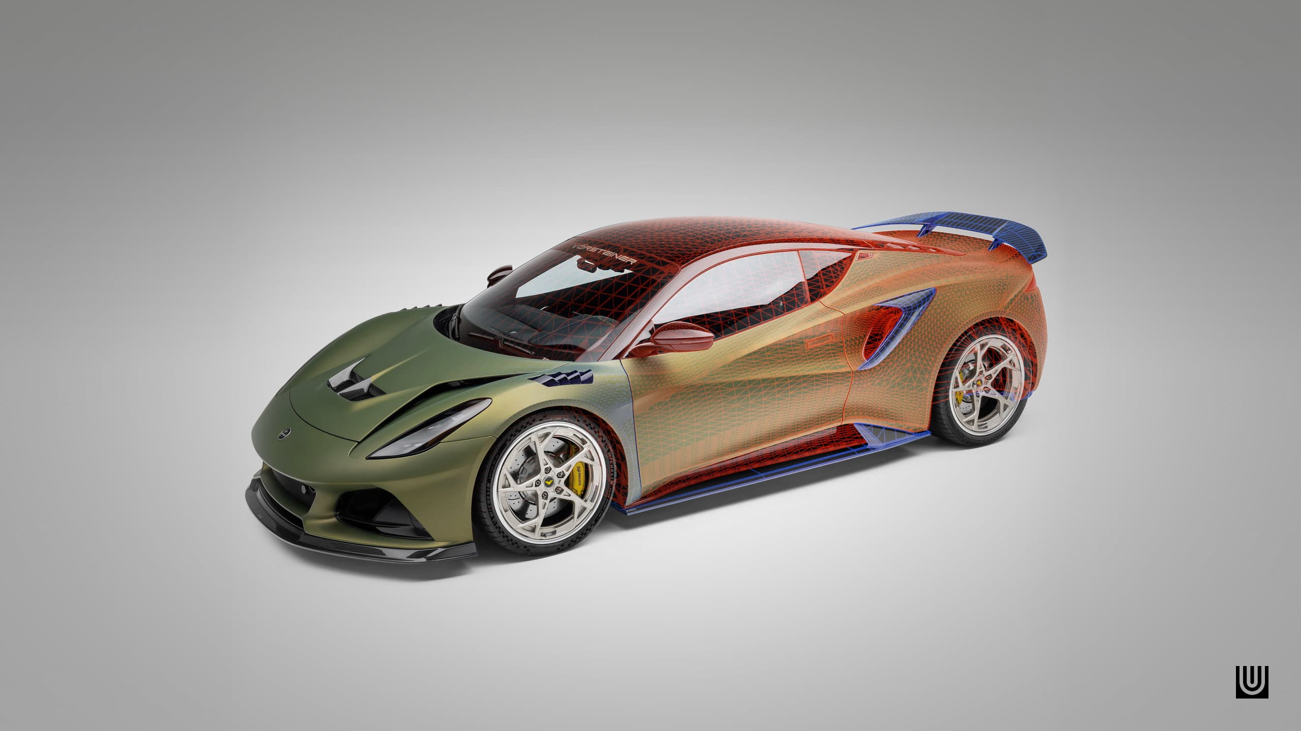
Fitting aftermarket widebody kits, carbon rear wings, or custom diffusers onto a base chassis can take hours of manual camera tweaking if your perspective is off. When I modeled the carbon fiber aero program for my Lotus Emira Vorsteiner LR-52 3D Model, getting the swan-neck rear wing and aggressive rear diffuser geometry to align perfectly with real-world photo references required precise camera solving.
If you want to skip guessing focal lengths, this guide shows you how to photomatch bodykits onto existing 3D base car models using camera-pnpoint—a free Blender add-on that automates camera solving using Perspective-n-Point math.
Digital Asset Disclaimer: All files discussed are digital 3D assets (
.BLEND,.OBJ,.FBX) meant for 3D visualization, game modding (Assetto Corsa, GTA V, BeamNG), and rendering. These are not physical car parts.
What is Perspective Matching (PnPoint) and Why Use It?
Traditional camera matching relies on vanishing lines (like perspective boxes or grid lines). That works fine for architectural renders, but modern sports cars are full of sweeping curves, complex carbon splitters, and rounded fender lines where vanishing points are hard to pinpoint.
The camera-pnpoint add-on uses Perspective-n-Point (PnP) algorithms. By pinning known 3D points on a base chassis to the exact same spots in a real-world reference photo, Blender automatically calculates the exact camera position, pitch, roll, and focal length used by the photographer.
Once your camera pose is locked, extruding custom aero panels or matching intricate carbon weave trim becomes a simple drag-and-snap process.
Required Tools
Before starting, gather the following tools:
- Blender (v3.0 or newer recommended).
- camera-pnpoint Add-on: Download it for free from RT Studios on Gumroad. Technical documentation is available on the camera-pnpoint GitHub repo.
- A Base 3D Chassis: You need a factory stock 3D chassis of your target vehicle to align your camera against.
Need a Base Model for Your Mod Build? If you don't have a clean chassis to build on, check out AutoMod Workshop. It's a massive community platform loaded with ready-to-use 3D base models and assets for modders. You can also join the AutoMod Workshop Discord to trade base models, ask technical questions, and share your modding progress with thousands of creators.
Step 1: Set Up Your Reference Image in the Motion Tracking Workspace
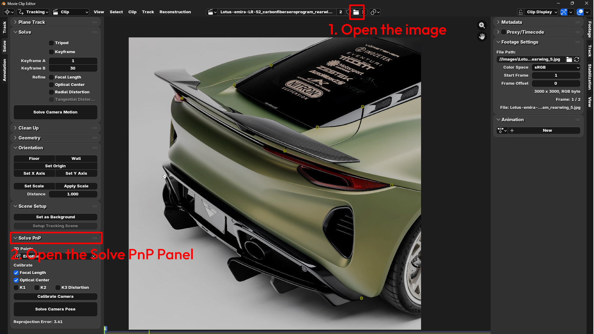
To set up PnPoint accurately, open your reference photo inside Blender's Motion Tracking interface:
- Switch to the Motion Tracking workspace at the top of Blender, or open a Movie Clip Editor panel in the top left of the viewport or by pressing
Shift + F2. - Click Open and load your high-res reference photo (e.g., a rear three-quarter shot of the Vorsteiner Lotus Emira).
- Under the Track panel on the left side, expand Solve PnP. This is where your 3D point parameters and camera solve controls live.
Step 2: Placed 2D Tracking Markers on Key Feature Points
Identify 6 to 8 hard, distinct feature points on the vehicle that exist on both your base 3D mesh and the photo reference, such as:
- Outer corners of the rear taillights
- Panel gaps and corners
- Badges with sharp angles
In the Movie Clip Editor, Ctrl + Right Click to place 2D track markers on those exact spots across the photo.

Step 3: Link 2D Markers to 3D Empties on Your Base Chassis
Now you need to tell Blender where those points exist in 3D space on your factory base model:
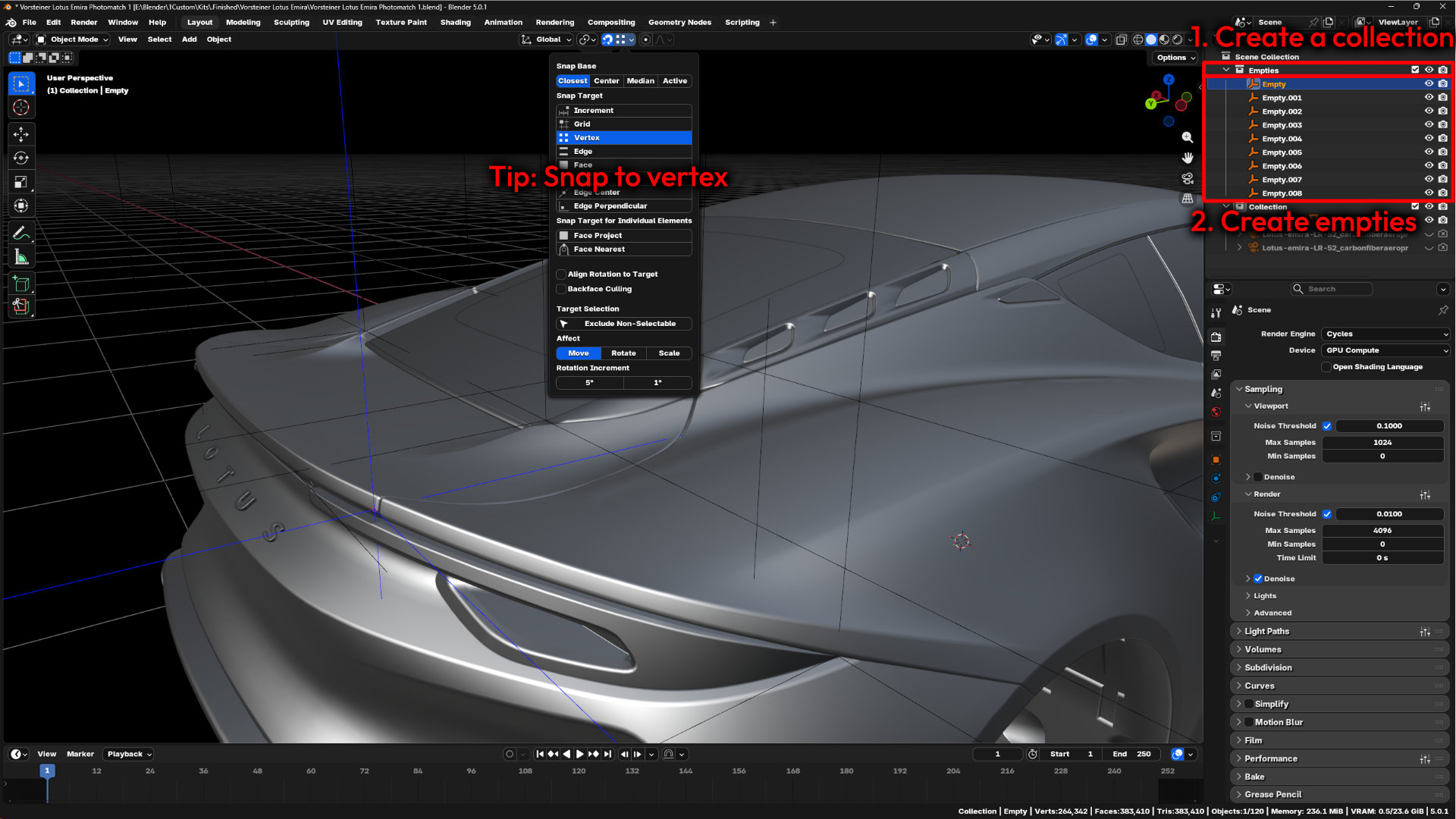
- In the Outliner, create a Collection to place your 3D empties in.
- In the 3D Viewport, create an Empty object (
Shift + A> Empty > Plain Axes) for every 2D point you created and put these in the collection. - Snap each Empty precisely to the corresponding vertex on your 3D base mesh (e.g., place
Empty.001right on the outer corner of the 3D taillight mesh). - Tip: Enable "Snap to vertex" to the accurate positions in your 3D Viewport.
- Make sure the number of the empties (e.g.
Empty.001) aligns with the previously placed tracking markers (e.g.Track.001)
Step 4: Calibrate and Solve Camera Pose
With your 2D photo coordinates linked to your 3D mesh coordinates:
- Under Calibrate in the Solve PnP panel, check Focal Length and Optical Center.
- Click Solve Camera Pose.
- Blender will process the Perspective-n-Point math and output a Reprojection Error value (aim for a value below 5.0 for accurate alignment).
Once solved, your active camera will snap to the exact position and focal length of the original photograph. Switch to Camera View (Numpad 0) to verify that your stock base chassis sits flush over the photo background.
Step 5: Model and Fit Aftermarket Aero Components
With your perspective locked, you can extrude custom bodykit panels directly over the reference photo:
- Lock your camera view so you don't accidentally rotate out of perspective while editing.
- Begin extruding geometry for your custom parts (like a swan-neck carbon wing or lower diffuser vanes) directly over the background photo.
Speeding Up Your Fitment Workflow
If you want to see how I handle wheel matching and alignment using a similar perspective process, check out my other guides:
- 🎬 Watch: How to Photomatch 3D Wheels in Blender
- 📖 Read: How I Streamlined 3D Wheel Modeling in Blender: Introducing Blender Wheel Tools
If you're looking for game-ready 3D wheels or custom aero parts for your mod builds, browse my full collection on my Virtual Shop.